
ERDC/CHL CHETN-I-70
May 2005
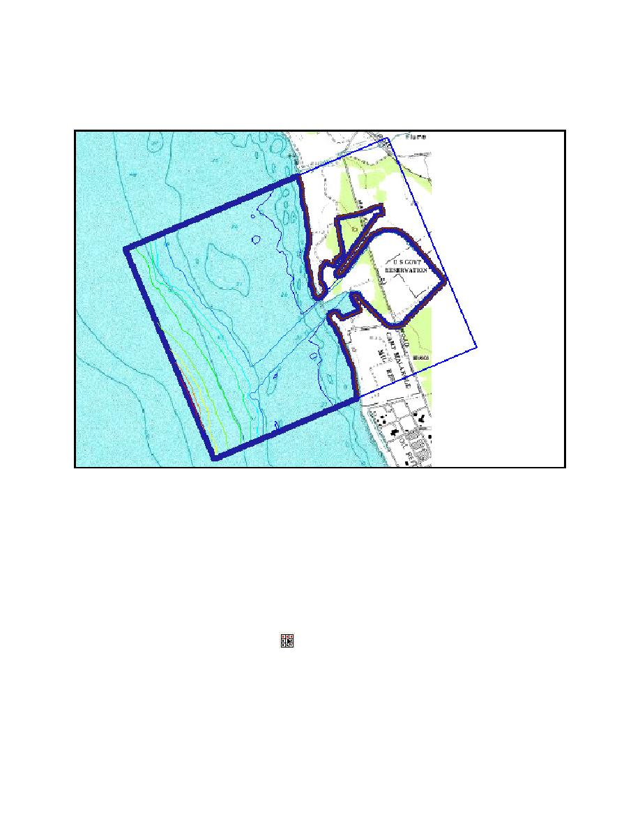
Figure 10 shows the resulting grid boundary. The computational (ocean) area is outlined in the
darker colors. The area on the right (land) is inactive, and model calculations are not performed in
the land regions.
Figure 10. Resulting grid
Define Wave Maker: The BOUSS-2D is a numerical wave tank, and the layout of its modeling
domain is similar to the setup of a laboratory (physical model) study. The BOUSS-2D wave maker
must be positioned along a straight line that can be referred to here as a "cell string" in the SMS
terminology, and at a desired location where depth is ideally constant. The previously defined grid
creation process automatically generates cell strings along the edges of the computational area. Cell
strings can also be created manually to specify the location of structures, wave makers, and areas
where damping and/or porosity layers may be necessary. To define a wave maker, follow these
steps:
a. Select the Select Cell String tool
.
b. Select the cell string (in red) on the left side of the grid as shown in Figure 11, where wave
maker is to be situated.
9

 Previous Page
