
ERDC/CHL CHETN-I-70
May 2005
EXAMPLE 2 MODELING WAVES AT A JETTIED INLET:
All the necessary steps have been shown in Example 1 for constructing a complete BOUSS-2D
simulation. In this example, the only discussion will be the creation of porosity layers that were not
used in the first example. For illustration purposes, porosity layers will be placed around one of the
jetties in this example. All other features to be considered in this application are the same as in
Example 1, and will therefore be omitted. To start a new project from an existing SMS application,
select the File|Delete All command to clear out the Barbers Point simulation. Now select the
File|Open command and choose the file IdealInlet.par to open the existing simulation of an ideal
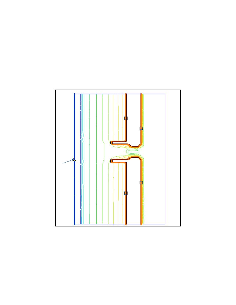
inlet that has a jetty on either side of the inlet. The modeling domain is shown in Figure 13. This grid
was generated following steps described in Example 1.
Figure 13. Ideal inlet test application
The existing grid was set up with the damping layers placed along the coastlines and around both
jetties. To be consistent, damping layers should be used for coastlines and porosity layers for
breakwaters and jetties. Porosity layers will be placed around the south jetty for modeling the
interaction of waves with a porous structure. The following steps can be used:
a. Select the cell string that goes along the south jetty.
13

 Previous Page
