ERDC/CHL CHETN-I-68
March 2004
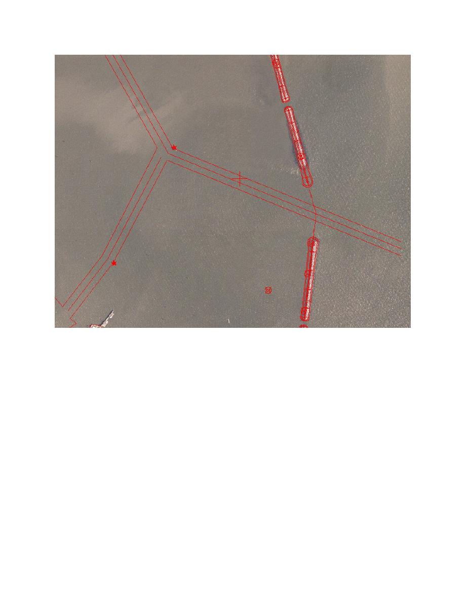
Figure 11. Schematic of existing breakwater configuration (121.9-m (400-ft) gap) versus red outline of
authorized breakwater alignment (91.4-m (300-ft) gap) with respect to channel outline
In the 1-D section, the user can specify either the number of nodes or the spacing in the 1-D lines.
The spacing should be of the order of the smallest element, typically closest to the coastline, on the
semicircle. A rule of thumb is that it is 1.25 times the offshore boundary radius divided by 100. The
length of 1-D lines should extend sufficiently offshore, and may extend to the limits of the existing
scatter set or further extended to pick up waves from buoys located beyond the scatter set. After
selecting appropriate accuracy, the user selects either the "#1-d nodes" or the "1-d spacing" in the
Compute section to calculate and save the 1-D lines (assuming the "Save 1-d file" under "Open
Boundary" has been selected).
Finally, the numerical solver should be selected for the machine performing the calculations. If the
model is small enough for the PC, then the "0 (or 1) Standard (PC)" solver(s) is selected. Otherwise,
the "2 SGI Parallel" solver for the HPC Ruby SGI processor should be selected. There are different
solvers for different HPC supercomputers, however.
RUN MODEL: Before running the model, save your file and make an additional backup copy with a
different name in case the file becomes corrupted. Select File | Save As to save the file as a project
file with suffix *.spr. All geometry, input, and mesh information is contained in this file.
16


 Previous Page
