
ERDC/CHL CHETN-IV-32
June 2001
crown of the cross-barrier pipe, a friction factor for the cross-barrier pipe, and the diameter of the
cross-barrier pipe for each of the internal barrier with cross-barrier pipe boundary-node pairs.
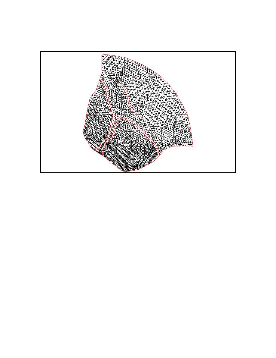
Figure 7. Domain definition and finite element grid for Example 20c
Flow boundary no. 8 has been implemented as a leaky boundary by specifying four node pairs as
having a pipe crown height located at PIPEHT = 0.3048 m (1.0 ft), a pipe friction factor
PIPECOEF = 0.1, and a pipe diameter PIPEDIAM = 0.6096 (2.0 ft). At all boundary node
pairs where no cross-barrier pipe flow is desired, a pipe crown height equal to 30.48 m (100 ft)
has been specified. Note that leakage is only initiated once the water level exceeds designated
pipe crown height, PIPEHT. The second barrier is designated in the unit 14 input file as flow
boundary no. 9 and encircles the western low-lying land region and has an internal-barrier
boundary height of 0.762 m (2.5 ft). Finally, the third is designated in the unit 14 input file as
flow boundary no. 10 and lies northeast of the river and has an internal-barrier boundary height
of 0.3048 m (1.0 ft). The finite-element grid and the bathymetry are shown in Figures 7 and 8,
respectively.
12

 Previous Page
