ERDC/CHL CHETN-IV-34
June 2001
Outer Wave
Breakers
Surf
Zone
q3
Wave
Crest
q4
q5
W
1
4
5
6
2 3
Channel
Channel Section
Centerline
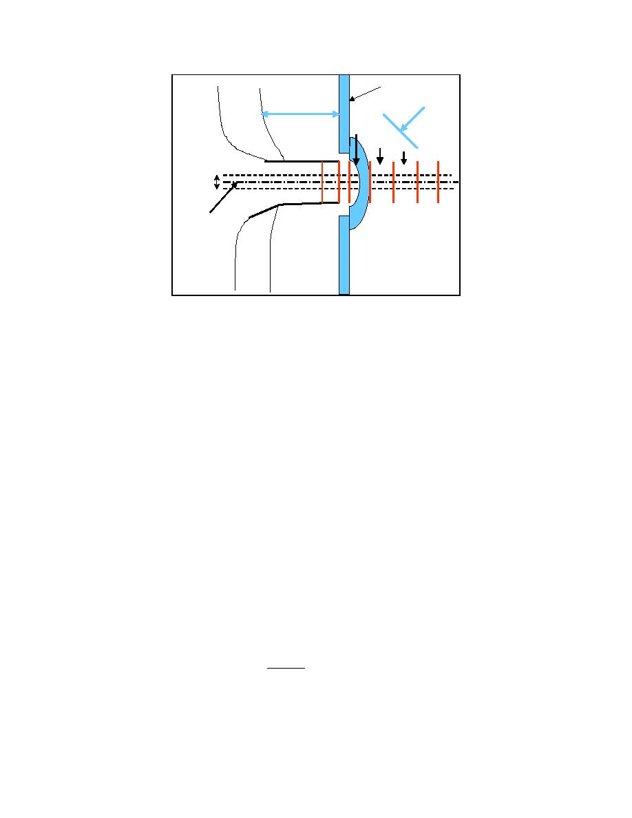
Figure 1. Planview sketch for channel transport sections
Transport at Channel: The transport rate qin at the updrift edge of the channel may be
calculated from the depth-averaged longshore current (current uniform through the water
column) and the suspended sediment concentration distribution according to the product,
ha
ha
qin = ∫ U aC ( z)dz = U a ∫ C ( z)dz
(1)
0
0
where Ua = depth-averaged velocity normal to the channel, C(z) = sediment concentration, z =
elevation from the surrounding (ambient) bed, and ha is the ambient depth adjacent to the
channel (Figure 2). The transport rate per unit length of channel may have to be divided into
sections as shown in Figure 1, according to the current, ambient depth, channel depth, and
presence of wave breaking.
Empirically, the sediment concentration profile in the surf zone has been found to decrease with
elevation from the bottom as an exponential shape,
C ( z) = Cb exp ( -λz / ha )
(2)
where Cb = concentration at the bed, and λ = dimensionless empirical suspended-sediment decay
coefficient (Kraus and Dean 1987). The transport rate of sediment suspended to a certain level zs
above the ambient bed adjacent to the channel is then found by integration to that elevation as:
zs
U aCbha
[1 - exp(-λzs / ha )]
qin ( zs ) = U a ∫ Cb exp ( -λz / ha ) dz =
(3)
λ
0
2


 Previous Page
