ERDC/CHL CHETN-IV-33
June 2001
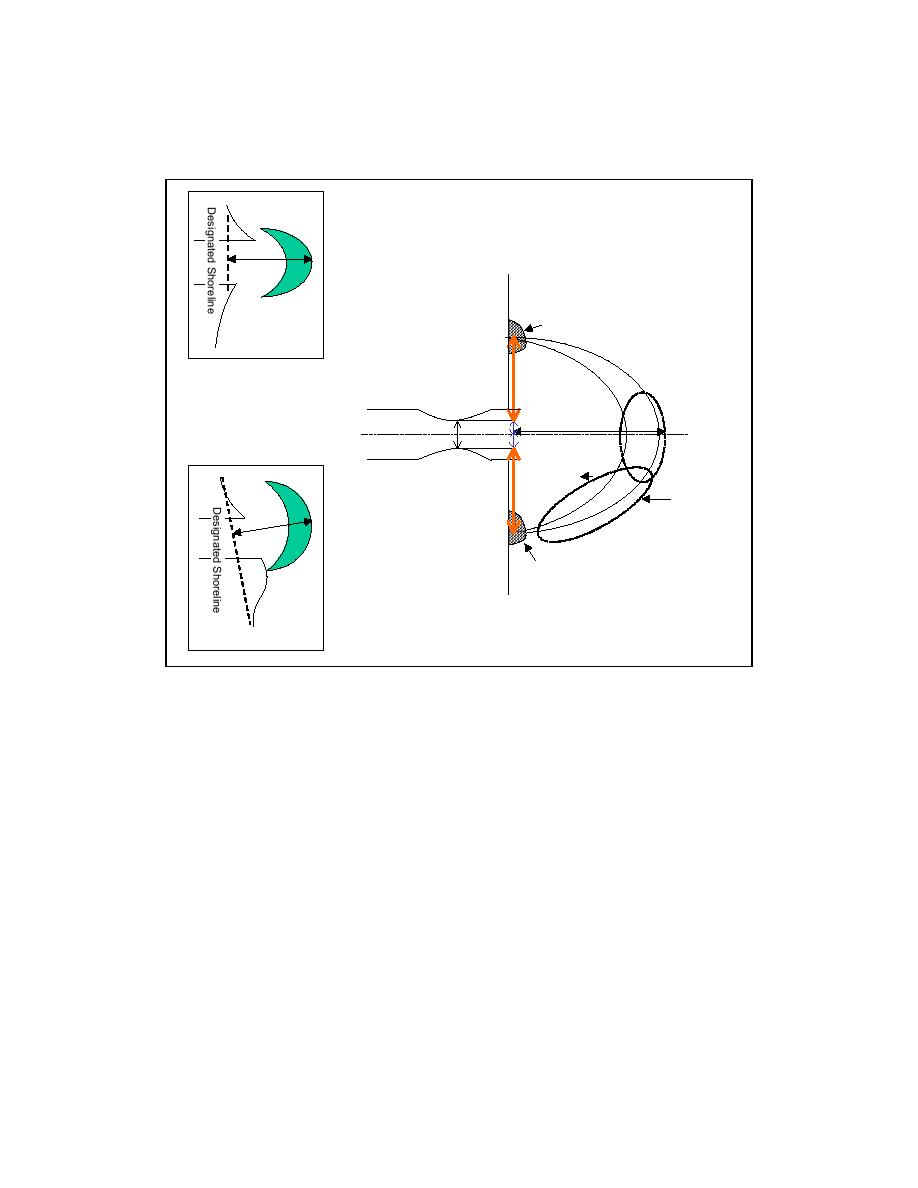
two landmasses on either side of the inlet. The variables WA1 and WA2 represent distances to the
updrift and downdrift attachment bars (where the bypassing bars tie in to the shore), respectively.
L
Updrift Attachment Bar
Updrift Offset
Bay
Ocean
WA1
Wc/2
L
Channel Center Line
Wc
Wc/2
Shoal
WA2
Bar
L
Downdrift Attachment Bar
Downdrift Offset
Figure 2. Symmetric ebb shoal with definitions of terminology used in measurements
The inset diagrams in Figure 2 represent the downdrift and updrift shoreline position offsets.
The shoreline, which defines the horizontal coordinate in the measurements, has been taken as a
line between the trends in updrift and downdrift shorelines. The line has been drawn to connect
the shorelines sufficiently far from the inlet to define a more regional trend. Measurements from
inlets with identified offsets were made in the same way as those with more uniform shorelines.
At inlets with two jetties, jetty length did not enter the measurement process. The jetties may
alter the shoreline position, in which case the preceding procedure was applied for defining the
shoreline trend.
Identification of the net direction of transport, determining which shoreline lies updrift and
which downdrift, is one of the first steps in applications such as development of a sediment
budget, bypassing requirements and, possibly, the alignment or realignment of the entrance
navigational channel. The direction of net longshore transport can usually be determined by
interpretation of the shoreline signature in aerial photographs. Impoundment and erosion at
jetties, growth of spits, asymmetry in the ebb shoal complex, orientation of the channel, and the
existence and location of attachment bars allow inferences of net transport direction to be made.
Caution must be taken to account for processes that may not be straightforward. Examples of
3


 Previous Page
