CETN IV-19
March 1999
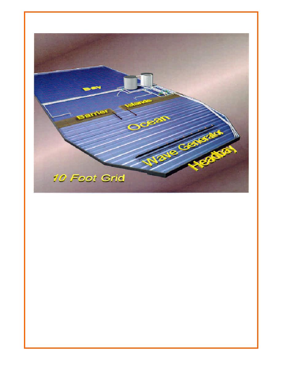
Figure 1. Oblique view of inlet model research facility
The minimum width is 244 cm across the inlet between mlw contours (or when scaled by 1:50,
represents a width of 122 m (400 ft)). Figure 2 shows the inlet throat and entrance channel with
parallel jetties that have a spacing of 3.66 m (12.0 ft) and extend 5.5 m (18 ft) offshore.
Based on Froude's model law (Hughes 1993), which requires equivalence of the expression
depth or length scale), and the linear scale of 1:50, the model-prototype relations in Table 1 were
derived. Dimensions are in terms of length (L) and time (T). Other scales may be assumed for
the bathymetry, so that different scaling relationships would apply than listed in Table 1.
The Idealized Inlet Facility is connected to a large sump (volume of 1.98 106 L (523,000 gal))
for water exchange so that tides may be produced in the ocean of the facility to drive tidal
currents into and out of the inlet bay. A constant inflow is introduced from the sump into the
model ocean while a "rolling" gate either reduces or increases flow area over an exit pipe into the
sump, which causes ocean rise or fall, respectively. The rolling gate is regulated by a controller
connected to a feedback loop comparing actual with desired water level. The two circular shapes
in the upper left corner of Figure 1 are storage tanks, each holding 182,000 L (48,000 gal) of
water. The tanks enable simulation of a much larger bay area by storing flood tide water and
2


 Previous Page
