
PROGRAM OUTPUT: UTEXAS2 generates table of input data providing a record of
the information used in the analysis, tables of search results listing the
circle center and the calculated safety factor for each circle evaluated, and
tables of details of the critical surface including the final safety factor.
It is recommended that hand checks of the critical circle be performed for all
final designs.
PROGRAM AVAILABILITY: The program is available for the IBM PC and may be
obtained from Ms. Gloria J. Naylor at (601) 634-2581), FTS: 542-2581,
Engineering Computer Programs Library Section, Technical Information Center,
U.S. Army Engineer Waterways Experiment Station, P.O. Box 631, Vicksburg,
Mississippi 39180-0631. Also it is available in the Corps library on both CDC
and Harris computers.
Questions concerning application of UTEXAS2 can be
directed to geotechnical engineers, in the field offices, or to Mr. Earl Edris
at (601) 634-3378 (FTS 542-3378) or Mr. Gordon E. Staab at (601) 634-2139
(FTS 542-2139). This program is for exclusive use of Corps of Engineers
personnel as it is a proprietary program. Any others wishing to we this
program should contact Mr. Stephen G. Wright, University of Texas.
SAMPLE PROBLEM: A steel sheet pile bulkhead with granular backfill, founded
upon soft clay, with a splash apron of concrete with a unit weight of 150
pounds per cubic foot, and with depth of water on its seaward face of 10 feet
was modeled.
SAMPLE RUN: UTEXAS2 searched numerous circles to determine minimum value of
factor of safety and parameters associated with final critical circle as shown
in fable 1.
************************************************
* FINAL RESULTS FOR SHEAR SURFACE (CRITICAL *
*
* SURFACE IN CASE OF A SEARCH)
*
*
*******************************************
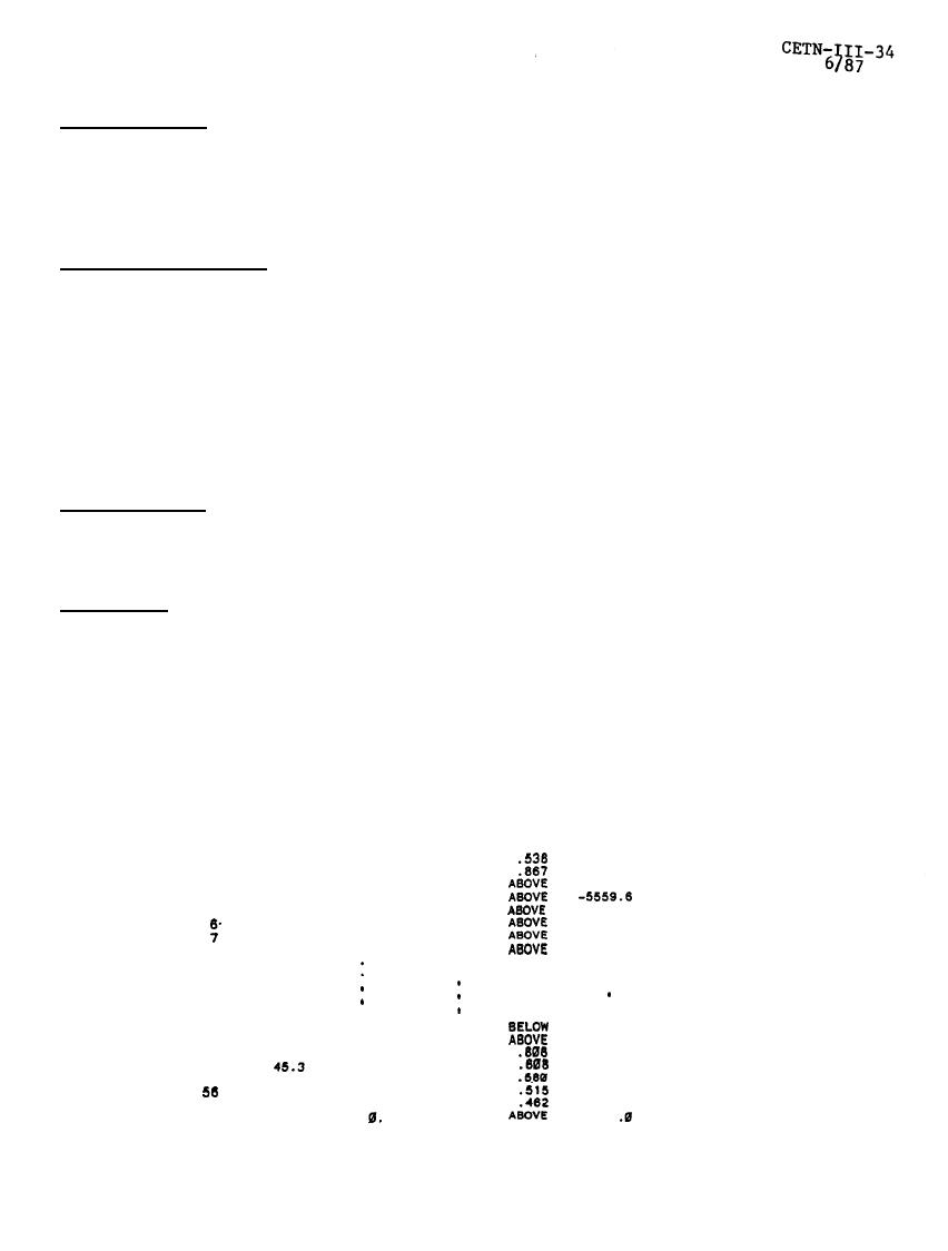
SPENCER'S PROCEDURE
USED TO COMPUTE FACTOR OF SAFETY
Side Force lncilnation
= 15.03
Degrees
Factor of Safety =
1.880
--------------------VALUES AT
RIGHT
SIDE
OF SLlCE------------------
Fraction
Sigma
Sigma
Y-Coord. of
Of
at
at
Side
Side Force
Slice
Bottom
Force
Height
Location
TOP
NO.
X-Right
-7293.5
-4711.9
1
3.9
-6759.
24.5
24.7
-8749.2
3287.3
2
4.2
-8103.
-6901.8
3596.1
25.1
3
4.6
-5493.
25.7
3341.5
4
5.1
-4867.
-4623.7
3070.2
-4216.
26.7
5
5.6
28.3
-3946.1
2848.3
5.2
-3540.
30.9
-3435.7
2668.9
8.8
-2843
-3038.1
2528.4
8
7.4
-2131.
35.7
.
.
.
.
.
,
.
.
.
.
.
.
.
.
.
.
.
.
.
.
13.7
-210.2
255.9
51
44.3
153.
-194.5
152.1
52
44.7
-120.
32.7
-287.
27.2
-180.0
53.1
53
45.0
-347.
28.7
-188.0
-36.1
54
-104.5
-57.9
55
45.4
-345.
26.7
27.1
-155.9
-130.7
-282.
45.6
-140.
27.6
-132.5
-210.8
57
46.8
35.8
.a
58
45.9
Table
1
3

 Previous Page
